
Routing Overview
flowchart TD
%% Node Utama
R[Routing]

    %% Sub-Node Jenis Routing
    SR[Static Routing]
    D_R[Default Routing]
    DY_R[Dynamic Routing]

    %% Jalur Hubungan Bercabang
    R --- SR
    R --- D_R
    R --- DY_R

    %% Styling untuk menyamakan warna teal/biru langit seperti gambar asli
    classDef tealBox fill:#90caf9,stroke:#0d47a1,stroke-width:1px,color:#1a237e;
    class R,SR,D_R,DY_R tealBox;
Routing is sending packet data from one network to another network. The device used in routing is a router. A router is used for best path selection and packets forwarding.
To get to the destination, a router can be configured in 2 ways:
- Manually, entering routes into the routing table manually (static routing).
- Dynamically, using routing protocols (dynamic routing).
Dynamic Routing vs Static Routing
| Dynamic Routing | Static Routing | |
|---|---|---|
| Configuration Complexity | Generally independent of the network size | Increases with the network size |
| Topology Changes | Automatically adapts to topology changes | Administrator intervention required |
| Scaling | Suitable for simple and complex topologies | Suitable for simple topologies |
| Security | Less secure | More secure |
| Resource Usage | Uses CPU, memory, link bandwidth | No extra resources needed |
| Predictability | Route depends on the current topology | Route to destination is always the same |
Static Routing#
In static routing, the network administrator enters routes into the routing table manually to reach a specific network. The configuration must be updated manually every time there is a topology change.
- Static Routing has an Administrative Distance (AD) of 1, so it will be preferred over dynamic routing.
- Better security, static routes are not advertised in the network.
- Uses less bandwidth than dynamic routing protocols, because it does not exchange routes.
- No CPU cycles are used to calculate and communicate routes.
- The path a static route uses to send data is known.
- Time-consuming configuration and maintenance.
- Not suitable for large-scale networks.
- For small networks where topology changes will not occur significantly.
- Routing to/from a stub network. A stub network is an accessed network that only has 1 exit path (because it only has one neighbor).
- For unknown networks using a default route.
ip route (space) destination network (space) subnetmask (space) ip/interface next-hop
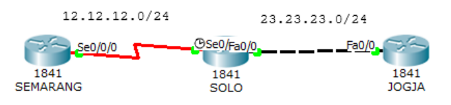
Create the topology below and configure the interfaces.
Router(config)#hostname SEMARANG
SEMARANG(config)#interface s0/0/0
SEMARANG(config-if)#ip address 12.12.12.1 255.255.255.0
SEMARANG(config-if)#no shutdown
Router(config)#hostname SOLO
SOLO(config)#interface s0/0/0
SOLO(config-if)#ip address 12.12.12.2 255.255.255.0
SOLO(config-if)#no shutdown
SOLO(config-if)#interface f0/0
SOLO(config-if)#ip address 23.23.23.2 255.255.255.0
SOLO(config-if)#no shutdownRouter(config)#hostname JOGJA
JOGJA(config)#interface f0/0
JOGJA(config-if)#ip address 23.23.23.3 255.255.255.0
JOGJA(config-if)#no shutdownConfigure static routing on the Semarang and Jogja routers. The Solo router does not need to be configured with static routing because it is directly connected to the Semarang and Jogja routers.
SEMARANG(config-if)#ip route 23.23.23.0 255.255.255.0 12.12.12.2
JOGJA(config-if)#ip route 12.12.12.0 255.255.255.0 23.23.23.2
Now check ping and look at the routing table.
JOGJA#ping 12.12.12.1
Type escape sequence to abort.
Sending 5, 100-byte ICMP Echos to 12.12.12.1, timeout is 2 seconds:
.!!!!
Success rate is 80 percent (4/5), round-trip min/avg/max = 3/6/17 ms

JOGJA#show ip route
Codes:  C - connected, S - static, I - IGRP, R - RIP, M - mobile, B - BGP
        D - EIGRP, EX - EIGRP external, O - OSPF, IA - OSPF inter area
        N1 - OSPF NSSA external type 1, N2 - OSPF NSSA external type 2
        E1 - OSPF external type 1, E2 - OSPF external type 2, E - EGP
        i - IS-IS, L1 - IS-IS level-1, L2 - IS-IS level-2, ia - IS-IS inter
area
        * - candidate default, U - per-user static route, o - ODR
        P - periodic downloaded static route

Gateway of last resort is not set

    12.0.0.0/24 is subnetted, 1 subnets
S       12.12.12.0 [1/0] via 23.23.23.2
    23.0.0.0/24 is subnetted, 1 subnets
C       23.23.23.0 is directly connected, FastEthernet0/0
JOGJA#
SEMARANG#ping 23.23.23.3
Type escape sequence to abort.
Sending 5, 100-byte ICMP Echos to 23.23.23.3, timeout is 2 seconds:
!!!!!
Success rate is 100 percent (5/5), round-trip min/avg/max = 1/4/14 ms
SEMARANG#sh ip route
Codes: C - connected, S - static, I - IGRP, R - RIP, M - mobile, B - BGP
D - EIGRP, EX - EIGRP external, O - OSPF, IA - OSPF inter area
N1 - OSPF NSSA external type 1, N2 - OSPF NSSA external type 2
E1 - OSPF external type 1, E2 - OSPF external type 2, E - EGP
i - IS-IS, L1 - IS-IS level-1, L2 - IS-IS level-2, ia - IS-IS inter
area
* - candidate default, U - per-user static route, o - ODR
P - periodic downloaded static route
Gateway of last resort is not set
12.0.0.0/24 is subnetted, 1 subnets
C 12.12.12.0 is directly connected, Serial0/0/0
23.0.0.0/24 is subnetted, 1 subnets
S 23.23.23.0 [1/0] via 12.12.12.2
SEMARANG#Static routing is indicated by the S mark. When tracerouted, it passes through 12.12.12.1 as the next-hop to the 23.23.23.0/24 network.
SEMARANG#traceroute 23.23.23.3
Type escape sequence to abort.
Tracing the route to 23.23.23.3

    1   12.12.12.2      0 msec      0 msec      0 msec
    2   23.23.23.3      1 msec      1 msec      4 msec
SEMARANG#
Default Routing#
Default routing is actually included in static routing. Commonly used for routing to the internet. In the routing table, default routing is always at the bottom and is always the last preferred.
ip route (space) 0.0.0.0 (space) 0.0.0.0 (space) ip/interface next-hop
Continuation of the previous lab. First, delete the static route that was previously created.
SEMARANG(config)#no ip route 23.23.23.0 255.255.255.0 12.12.12.2
JOGJA(config)#no ip route 12.12.12.0 255.255.255.0 23.23.23.2
Now enter the default routing.
SEMARANG(config)#ip route 0.0.0.0 0.0.0.0 12.12.12.2
JOGJA(config)#ip route 0.0.0.0 0.0.0.0 23.23.23.2
Now test ping and check the routing table.
SEMARANG#ping 23.23.23.3

Type escape sequence to abort.
Sending 5, 100-byte ICMP Echos to 23.23.23.3, timeout is 2 seconds:
!!!!!
Success rate is 100 percent (5/5), round-trip min/avg/max = 1/1/1 ms

SEMARANG#sh ip route
Codes:  C - connected, S - static, I - IGRP, R - RIP, M - mobile, B - BGP
        D - EIGRP, EX - EIGRP external, O - OSPF, IA - OSPF inter area
        N1 - OSPF NSSA external type 1, N2 - OSPF NSSA external type 2
        E1 - OSPF external type 1, E2 - OSPF external type 2, E - EGP
        i - IS-IS, L1 - IS-IS level-1, L2 - IS-IS level-2, ia - IS-IS inter
area
        * - candidate default, U - per-user static route, o - ODR
        P - periodic downloaded static route

Gateway of last resort is 12.12.12.2 to network 0.0.0.0

    12.0.0.0/24 is subnetted, 1 subnets
C       12.12.12.0 is directly connected, Serial0/0/0
S*  0.0.0.0/0 [1/0] via 12.12.12.2
SEMARANG#
Default routing is indicated by the S* mark and the destination 0.0.0.0/0 which means to all IPs.
Dynamic Routing Overview#
flowchart TD
%% Node Utama
DRP[Dynamic Routing Protocol]

    %% Kategori Utama (IGP & EGP)
    IGP["Interior Gateway Protocol (IGP)"]
    EGP["Exterior Gateway Protocol (EGP)"]

    DRP --- IGP
    DRP --- EGP

    %% Klasifikasi IGP
    DV[Distance Vector]
    LS[Link State]

    IGP --- DV
    IGP --- LS

    %% Klasifikasi EGP
    PV[Path Vector]

    EGP --- PV

    %% Protokol Distance Vector
    RIP1[RIPv1]
    RIP2[RIPv2]
    IG[IGRP]
    EI[EIGRP]

    DV --- RIP1
    RIP1 --- RIP2
    DV --- IG
    IG --- EI

    %% Protokol Link State
    OSPF[OSPF]
    ISIS[IS-IS]

    LS --- OSPF
    LS --- ISIS

    %% Protokol Path Vector
    BGP[BGP]

    PV --- BGP

    %% Styling menyesuaikan warna biru muda dari diagram asli
    classDef blueBox fill:#d6eaf8,stroke:#5dade2,stroke-width:1.5px,color:#17202a;
    class DRP,IGP,EGP,DV,LS,PV,RIP1,RIP2,IG,EI,OSPF,ISIS,BGP blueBox;
Dynamic routing uses routing protocols in forming the routing table. When the topology changes, the routing table will automatically change.
- Uses more bandwidth than static routing, because of route exchanging.
- CPU cycles are used to calculate and communicate routes.
- Suitable for large-scale networks.
ROUTING PROTOCOL COMPARISON#
| RIP v1 | RIP v2 | IGRP | EIGRP | OSPF | IS-IS | BGP | |
|---|---|---|---|---|---|---|---|
| Interior/Exterior? | Interior | Interior | Interior | Interior | Interior | Interior | Exterior |
| Type | Distance Vector | Distance Vector | Distance Vector | Hybrid | Link-state | Link-state | Path Vector |
| Default Metric | Hopcount | Hopcount | Bandwidth/Delay | Bandwidth/Delay | Cost | Cost | Multiple Attributes |
| Administrative Distance | 120 | 120 | 100 | 90 (internal) 170 (external) | 110 | 115 | 20 (external) 200 (internal) |
| Hopcount Limit | 15 | 15 | 255 (100 default) | 224 (100 default) | None | None | EBGP Neighbors: 1 (default) IBGP Neighbors: None |
| Convergence | Slow | Slow | Slow | Very Fast | Fast | Fast | Average |
| Update timers | 30 seconds | 30 seconds | 90 seconds | Only when change occurs | Only when changes occur; (LSA table is refreshed every 30 minutes, however) | Only when changes occur | Only when changes occur |
| Updates | Full table | Full table | Full table | Only Changes | Only Changes | Only changes | Only changes |
| Classless | No | Yes | No | Yes | Yes | Yes | Yes |
| Supports VLSM | No | Yes | No | Yes | Yes | Yes | Yes |
| Algorithm | Bellman-Ford | Bellman-Ford | Bellman-Ford | DUAL | Dijkstra | Dijkstra | Best Path Algorithm |
| Update Address | Broadcast | 224.0.0.9 | 224.0.0.10 | 224.0.0.10 | 224.0.0.5 (All SPF Routers) 224.0.0.6 (DR’s and BDR’s) | Unicast | |
| Protocol and Port | UDP port 520 | IP Protocol 9 | IP Protocol 88 | IP Protocol 89 | TCP port 179 |
IGP and EGP#
The internet is composed of many AS. Imagine the internet is like a puzzle, then the AS are the puzzle pieces. And on the internet there are thousands of AS. AS or Autonomous System itself is a collection of routers within the same authority.
Interior Gateway Protocol (IGP) is used for routing within an AS (IntraAS). IGP is used for internal networks within a company, organization, or service provider. IGP is also divided into 2 types:
- Distance Vector
As the name implies, there are 2 main characteristics in determining its route.
Distance = the distance of the source network to the destination based on the metric. The metric is calculated from hop count, cost, bandwidth, delay, etc.
Vector = the direction of the next hop router to reach the destination.
Distance Vector type protocols only know the route and metric to reach a certain destination. These protocols do not have information about the network map or topology as a whole.
Those included in the distance vector routing protocol: RIPv1, RIPv2, IGRP, and EIGRP.
- Link-State
Link-state type protocols know the overall network topology by collecting information from each router. For large-scale networks, link-state is designed hierarchically or divided into areas. The area that must exist in link-state is area 0 or the backbone. The division into these areas aims to reduce router resources with each area having a different routing table from other areas.
Those included in the link-state routing protocol: OSPF and IS-IS.
Exterior Gateway Protocol (EGP) is used for routing between AS (Inter AS). The only EGP protocol is BGP. BGP is a path-vector type protocol. The route generated from BGP contains the as-path attribute. AS Path is a sequence of AS Numbers passed by a route to reach the destination.
Enhanced Interior Gateaway Protocol (EIGRP)#
- Cisco proprietary
- Advanced distance vector/hybrid routing protocol
- Using DUAL Algorithm.
- Multicast or unicast for exchange information use port 88
- Administrative distance 90
- Classless routing protocol support VLSM/CIDR.
- Support IPv6
- Rich metric (bandwidth, delay, load and reliability)
- Very fast convergence
- Equal and Unequal Load balancing
- 100% loop-free
Configure interfaces as in the static routing lab and add loopback interfaces on the three routers. The loopback interface can be used as an identity and as a logical IP.
SEMARANG(config)#int lo0
SEMARANG(config-if)#ip address 1.1.1.1 255.255.255.255
SOLO(config)#int lo0
SOLO(config-if)#ip add 2.2.2.2 255.255.255.255
JOGJA(config)#int lo0
JOGJA(config-if)#ip add 3.3.3.3 255.255.255.255
Configure EIGRP on the routers. The AS Number in all EIGRP routers must be the same.
SEMARANG(config)#router eigrp ?
    <1-65535> Autonomous system number

SEMARANG(config)#router eigrp 10
SEMARANG(config-router)#network 12.12.12.0 ?
    A.B.C.D EIGRP wild card bits
    <cr>
SEMARANG(config-router)#network 12.12.12.0 0.0.0.255
SEMARANG(config-router)#network 1.1.1.1 0.0.0.0
SEMARANG(config-router)#no auto-summary
SEMARANG(config-router)#ex
SOLO(config)#router eigrp 10
SOLO(config-router)#network 12.12.12.0 0.0.0.255
SOLO(config-router)#network 23.23.23.0 0.0.0.255
SOLO(config-router)#network 2.2.2.2 0.0.0.0
SOLO(config-router)#no auto-summaryJOGJA(config)#router eigrp 10
JOGJA(config-router)#network 23.23.23.0 0.0.0.255
JOGJA(config-router)#network 3.3.3.3 0.0.0.0
JOGJA(config-router)#no auto-summaryNo-auto summary aims to include the subnet mask in EIGRP routing. Now perform a ping test and traceroute to the Jogja router.
SEMARANG#ping 2.2.2.2

Type escape sequence to abort.
Sending 5, 100-byte ICMP Echos to 2.2.2.2, timeout is 2 seconds:
!!!!!
Success rate is 100 percent (5/5), round-trip min/avg/max = 1/3/12 ms

SEMARANG#ping 3.3.3.3

Type escape sequence to abort.
Sending 5, 100-byte ICMP Echos to 3.3.3.3, timeout is 2 seconds:
!!!!!
Success rate is 100 percent (5/5), round-trip min/avg/max = 1/3/11 ms

SEMARANG#traceroute 3.3.3.3
Type escape sequence to abort.
Tracing the route to 3.3.3.3

    1   12.12.12.2      0 msec      2 msec      2 msec
    2   23.23.23.3      1 msec      0 msec      1 msec
SEMARANG#
Checking the routing table.
SEMARANG#sh ip route

Gateway of last resort is not set

        1.0.0.0/8 is variably subnetted, 2 subnets, 2 masks
D           1.0.0.0/8 [90/2809856] via 12.12.12.2, 00:07:37, Serial0/0/0
C           1.1.1.1/32 is directly connected, Loopback0
        2.0.0.0/32 is subnetted, 1 subnets
D           2.2.2.2 [90/2297856] via 12.12.12.2, 00:07:37, Serial0/0/0
        3.0.0.0/32 is subnetted, 1 subnets
D           3.3.3.3 [90/2300416] via 12.12.12.2, 00:02:48, Serial0/0/0
        12.0.0.0/24 is subnetted, 1 subnets
C           12.12.12.0 is directly connected, Serial0/0/0
        23.0.0.0/24 is subnetted, 1 subnets
D           23.23.23.0 [90/2172416] via 12.12.12.2, 00:02:49, Serial0/0/0
SEMARANG#
SOLO#sh ip route
Gateway of last resort is not set
1.0.0.0/8 is variably subnetted, 2 subnets, 2 masks
D 1.0.0.0/8 is a summary, 00:08:13, Null0
D 1.1.1.1/32 [90/2297856] via 12.12.12.1, 00:08:07, Serial0/0/0
2.0.0.0/32 is subnetted, 1 subnets
C 2.2.2.2 is directly connected, Loopback0
3.0.0.0/32 is subnetted, 1 subnets
D 3.3.3.3 [90/156160] via 23.23.23.3, 00:03:19, FastEthernet0/0
12.0.0.0/24 is subnetted, 1 subnets
C 12.12.12.0 is directly connected, Serial0/0/0
23.0.0.0/24 is subnetted, 1 subnets
C 23.23.23.0 is directly connected, FastEthernet0/0
SOLO#JOGJA#sh ip route
Gateway of last resort is not set
1.0.0.0/8 is variably subnetted, 2 subnets, 2 masks
D 1.0.0.0/8 [90/2300416] via 23.23.23.2, 00:03:39, FastEthernet0/0
D 1.1.1.1/32 [90/2300416] via 23.23.23.2, 00:03:39, FastEthernet0/0
2.0.0.0/32 is subnetted, 1 subnets
D 2.2.2.2 [90/156160] via 23.23.23.2, 00:03:39, FastEthernet0/0
3.0.0.0/32 is subnetted, 1 subnets
C 3.3.3.3 is directly connected, Loopback0
12.0.0.0/24 is subnetted, 1 subnets
D 12.12.12.0 [90/2172416] via 23.23.23.2, 00:03:39, FastEthernet0/0
23.0.0.0/24 is subnetted, 1 subnets
C 23.23.23.0 is directly connected, FastEthernet0/0
JOGJA#The D mark indicates that the route is generated through the EIGRP protocol. The AD on EIGRP is 90 marked in yellow and the metric is marked in blue. Metric calculation uses its own formula.
Open Shortest Path First (OSPF)#
- Open Standard.
- Link-State routing protocol.
- Using SPF/Dijkstra Algorithm.
- Multicast for exchange information use port 89.
- Administrative distance 110.
- Classless routing protocol support VLSM/CIDR.
- Support IPv6.
- Metric using cost.
- Fast convergence.
- Equal load balancing only.
- Using areas (backbone area and non-backbone areas).
Delete the previous EIGRP configuration.
SEMARANG(config)# no router eigrp 10
SOLO(config)# no router eigrp 10
JOGJA(config-if)# no router eigrp 10
Configure OSPF on the router. OSPF uses a process ID. The process ID on each router does not have to be the same, the most important thing is the area. To connect between one area and another it must pass through area 0 or the backbone area.
SEMARANG(config)#router ospf ?
    <1-65535> Process ID
SEMARANG(config)#router ospf 1
SEMARANG(config-router)#net
SEMARANG(config-router)#network 12.12.12.0 ?
    A.B.C.D OSPF wild card bits
SEMARANG(config-router)#network 12.12.12.0 0.0.0.255 area 0
SEMARANG(config-router)#network 1.1.1.1 0.0.0.0 area 0
SOLO(config)#router ospf 2
SOLO(config-router)#network 12.12.12.0 0.0.0.255 area 0
SOLO(config-router)#network 23.23.23.0 0.0.0.255 area 1
SOLO(config-router)#network 2.2.2.2 0.0.0.0 area 0JOGJA(config)#router ospf 3
JOGJA(config-router)#network 23.23.23.0 0.0.0.255 area 1
JOGJA(config-router)#network 3.3.3.3 0.0.0.0 area 1Now do a ping test.
SEMARANG#ping 2.2.2.2

Type escape sequence to abort.
Sending 5, 100-byte ICMP Echos to 2.2.2.2, timeout is 2 seconds:
!!!!!
Success rate is 100 percent (5/5), round-trip min/avg/max = 1/1/2 ms

SEMARANG#ping 3.3.3.3

Type escape sequence to abort.
Sending 5, 100-byte ICMP Echos to 3.3.3.3, timeout is 2 seconds:
!!!!!
Success rate is 100 percent (5/5), round-trip min/avg/max = 1/2/7 ms

SEMARANG#
Check the routing table.
SEMARANG#sh ip route

Gateway of last resort is not set

        1.0.0.0/32 is subnetted, 1 subnets
C           1.1.1.1 is directly connected, Loopback0
        2.0.0.0/32 is subnetted, 1 subnets
O           2.2.2.2 [110/65] via 12.12.12.2, 00:02:45, Serial0/0/0
        3.0.0.0/32 is subnetted, 1 subnets
O IA        3.3.3.3 [110/66] via 12.12.12.2, 00:01:21, Serial0/0/0
        12.0.0.0/24 is subnetted, 1 subnets
C           12.12.12.0 is directly connected, Serial0/0/0
        23.0.0.0/24 is subnetted, 1 subnets
O IA        23.23.23.0 [110/65] via 12.12.12.2, 00:03:13, Serial0/0/0
SOLO#sh ip ro
Gateway of last resort is not set
1.0.0.0/32 is subnetted, 1 subnets
O 1.1.1.1 [110/65] via 12.12.12.1, 00:05:40, Serial0/0/0
2.0.0.0/32 is subnetted, 1 subnets
C 2.2.2.2 is directly connected, Loopback0
3.0.0.0/32 is subnetted, 1 subnets
O 3.3.3.3 [110/2] via 23.23.23.3, 00:02:35, FastEthernet0/0
12.0.0.0/24 is subnetted, 1 subnets
C 12.12.12.0 is directly connected, Serial0/0/0
23.0.0.0/24 is subnetted, 1 subnets
C 23.23.23.0 is directly connected, FastEthernet0/0
SOLO#JOGJA#sh ip route
Gateway of last resort is not set
1.0.0.0/32 is subnetted, 1 subnets
O IA 1.1.1.1 [110/66] via 23.23.23.2, 00:02:03, FastEthernet0/0
2.0.0.0/32 is subnetted, 1 subnets
O IA 2.2.2.2 [110/2] via 23.23.23.2, 00:02:03, FastEthernet0/0
3.0.0.0/32 is subnetted, 1 subnets
C 3.3.3.3 is directly connected, Loopback0
12.0.0.0/24 is subnetted, 1 subnets
O IA 12.12.12.0 [110/65] via 23.23.23.2, 00:02:03, FastEthernet0/0
23.0.0.0/24 is subnetted, 1 subnets
C 23.23.23.0 is directly connected, FastEthernet0/0
JOGJA#The O mark indicates that the route is generated through the OSPF protocol. The IA mark indicates that the destination route is in a different area. The AD on OSPF is 110.
Access List (ACL)
Access List (ACL) is commonly used for filtering. There are 2 types of access lists, namely standard and extended.
| Standard ACL | Extended ACL |
|---|---|
| ACL Number range 1-99 | ACL Number range 100-199 |
| Can block a network, host and subnet | Can allow or deny a network, host, subnet and service |
| All service are blocked | Select service can be blocked |
| Implemented closest to the destination | Implemented closest to the destination |
| Filtering based on source IP address only | Filtering based on source IP address, destination IP, protocol and port number |
Standard Access List#
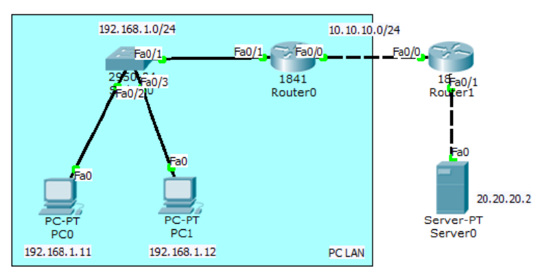
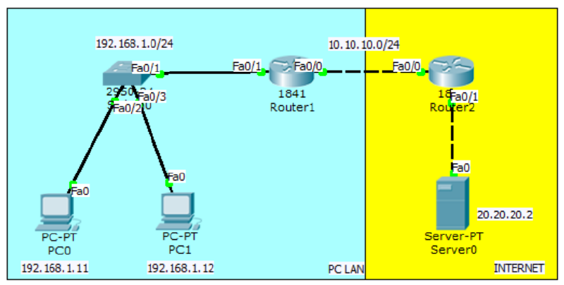
Perform configuration so that the LAN PC can ping the server.
Interface and routing configuration on Router0.
Router(config)#int fa0/1
Router(config-if)#ip add 192.168.1.1 255.255.255.0
Router(config-if)#no sh
Router(config-if)#int fa0/0
Router(config-if)#ip add 10.10.10.1 255.255.255.0
Router(config-if)#no sh
Router(config-if)#ip route 20.20.20.0 255.255.255.0 10.10.10.2
Interface and routing configuration on Router1.
Router(config)#int fa0/0
Router(config-if)#ip add 10.10.10.2 255.255.255.0
Router(config-if)#no sh
Router(config-if)#int fa0/1
Router(config-if)#ip add 20.20.20.1 255.255.255.0
Router(config-if)#no sh
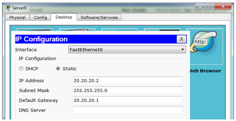
Router(config-if)#ip route 192.168.1.0 255.255.255.0 10.10.10.1Provide an IP on the server and try checking the web server via browser on the LAN PC.
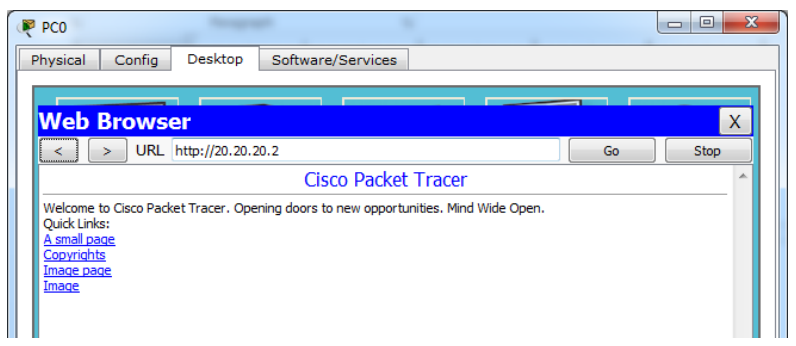
Check ping from the LAN PC to the web server.
PC>ping 20.20.20.2

Pinging 20.20.20.2 with 32 bytes of data:

Reply from 20.20.20.2: bytes=32 time=0ms TTL=126
Reply from 20.20.20.2: bytes=32 time=0ms TTL=126
Reply from 20.20.20.2: bytes=32 time=0ms TTL=126
Reply from 20.20.20.2: bytes=32 time=0ms TTL=126

Ping statistics for 20.20.20.2:
    Packets: Sent = 4, Received = 4, Lost = 0 (0% loss),
Approximate round trip times in milli-seconds:
    Minimum = 0ms, Maximum = 0ms, Average = 0ms
PC>
Now configure a standard access list so that the LAN PC cannot access the web server. Set the access list on the router and interface closest to the destination.
Router(config)#access-list 10 deny 192.168.10.0 ?
    A.B.C.D Wildcard bits
    <cr>
Router(config)#access-list 10 deny 192.168.1.0 0.0.0.255
Router(config)#access-list 10 permit any
Router(config)#int fa0/1
Router(config-if)#ip access-group 1 out
Check ping and browser access from the LAN PC to the web server.
PC>ping 20.20.20.2

Pinging 20.20.20.2 with 32 bytes of data:

Reply from 10.10.10.2: Destination host unreachable.
Reply from 10.10.10.2: Destination host unreachable.
Reply from 10.10.10.2: Destination host unreachable.
Reply from 10.10.10.2: Destination host unreachable.

Ping statistics for 20.20.20.2:
    Packets: Sent = 4, Received = 0, Lost = 4 (100% loss),
PC>
Check the access list on Router1.
Router#show access-lists
Standard IP access list 10
    deny 192.168.1.0 0.0.0.255 (64 match(es))
    permit any (5 match(es))
Router#
In a standard access list, all services will be blocked, whether UDP for browser access or ICMP for ping. To select only specific services, use an extended access list.
Extended Access List#
An extended access list allows only specific services to be blocked. The image below shows the types of services and their applications.
flowchart TD
%% Node Utama
IP[IP]

    %% Protokol Layer Transport/Network
    TCP[TCP]
    UDP[UDP]
    ICMP[ICMP]

    IP --- TCP
    IP --- UDP
    IP --- ICMP

    %% Aplikasi di bawah TCP
    HTTP[HTTP]
    TELNET[TELNET]
    FTP[FTP]
    SNTP[SNTP]

    TCP --- HTTP
    TCP --- TELNET
    TCP --- FTP
    TCP --- SNTP

    %% Aplikasi di bawah UDP
    DNS[DNS]
    TDTP[TDTP]
    DHCP[DHCP]
    NNTP[NNTP]

    UDP --- DNS
    UDP --- TDTP
    UDP --- DHCP
    UDP --- NNTP

    %% Aplikasi di bawah ICMP
    PING[PING]
    TRACE[TRACEROUTE]

    ICMP --- PING
    ICMP --- TRACE

    %% Styling Warna Biru
    classDef mainBox fill:#5b9bd5,stroke:#2e75b6,stroke-width:2px,color:#ffffff,font-weight:bold;
    classDef subBox fill:#ddebf7,stroke:#5b9bd5,stroke-width:1px,color:#000000;

    class IP,TCP,UDP,ICMP mainBox;
    class HTTP,TELNET,FTP,SNTP,DNS,TDTP,DHCP,NNTP,PING,TRACE subBox;
Still using the topology from the previous lab. First, delete the standard access list that was created on Router1.
Router(config)#no access-list 10Configure an extended access list on Router1 so that the LAN PC can access the web server but cannot ping.
Router(config)#access-list 100 deny icmp 192.168.1.0 0.0.0.255 host
20.20.20.2 echo
Router(config)#access-list 100 permit ip any any
Router(config)#int fa0/1
Router(config-if)#ip access-group 100 out
Try checking the browser and test ping.
PC>ping 20.20.20.2

Pinging 20.20.20.2 with 32 bytes of data:

Reply from 10.10.10.2: Destination host unreachable.
Reply from 10.10.10.2: Destination host unreachable.
Reply from 10.10.10.2: Destination host unreachable.
Reply from 10.10.10.2: Destination host unreachable.

Ping statistics for 20.20.20.2:
    Packets: Sent = 4, Received = 0, Lost = 4 (100% loss),
PC>
Check the access list.
Router#show access-lists
Standard IP access list 10
    deny 192.168.1.0 0.0.0.255 (64 match(es))
    permit any (5 match(es))
Router#
Network Address Translation (NAT)
Network Address Translation (NAT) is used to translate private IPs to public IPs or vice versa. Suppose there is a server in a company, besides being accessible locally, the company wants the server to be accessible via the internet. Then the server is given a public IP and configured with static NAT.
In NAT configuration, interfaces are set into 2 categories: inside and outside.
- Inside = traffic entering the router interface from the local network.
- Outside = traffic leaving through the router interface to the destination/internet.
There are several types of NAT.
- Static NAT, one private IP is translated to one public IP (one to one mapping).
- Dynamic NAT, the number of public IPs provided must be equal to the number of private IPs translated. This type of NAT is rarely used.
- Overloading/Port Address Translation (PAT), internet access using 1 public IP. This is widely used today.
Static NAT#
In static NAT, only 1 private IP is translated to 1 public IP. This means only 1 LAN PC can access the internet.
The configuration is almost the same as the access list lab, but it does not need to be routed because it will later use NAT.
Interface and routing configuration on Router1.
Router(config)#int fa0/1
Router(config-if)#ip add 192.168.1.1 255.255.255.0
Router(config-if)#no sh
Router(config-if)#int fa0/0
Router(config-if)#ip add 10.10.10.1 255.255.255.0
Router(config-if)#no sh
Interface and routing configuration on Router2.
Router(config)#int fa0/0
Router(config-if)#ip add 10.10.10.2 255.255.255.0
Router(config-if)#no sh
Router(config-if)#int fa0/1
Router(config-if)#ip add 20.20.20.1 255.255.255.0
Router(config-if)#no sh
Static NAT and default route configuration on R1. LAN PC 192.168.1.11 will be translated to public IP 10.10.10.10.
Router(config)#ip nat inside source ?
    list Specify access list describing local addresses
    static Specify static local->global mapping
Router(config)#ip nat inside source static 192.168.1.11 10.10.10.10
Router(config)#int fa0/1
Router(config-if)#ip nat inside
Router(config-if)#int fa0/0
Router(config-if)#ip nat outside
Router(config)#ip route 0.0.0.0 0.0.0.0 fa0/0
Ping static NAT through the server and vice versa. The LAN PC address can never be pinged from the internet.
SERVER>ping 10.10.10.10

Pinging 10.10.10.10 with 32 bytes of data:

Reply from 10.10.10.10: bytes=32 time=11ms TTL=126
Reply from 10.10.10.10: bytes=32 time=0ms TTL=126
Reply from 10.10.10.10: bytes=32 time=0ms TTL=126
Reply from 10.10.10.10: bytes=32 time=11ms TTL=126

Ping statistics for 10.10.10.10:
    Packets: Sent = 4, Received = 4, Lost = 0 (0% loss),
Approximate round trip times in milli-seconds:
    Minimum = 0ms, Maximum = 11ms, Average = 5ms

SERVER>ping 192.168.1.11

Pinging 192.168.1.11 with 32 bytes of data:

Reply from 20.20.20.1: Destination host unreachable.
Reply from 20.20.20.1: Destination host unreachable.
Request timed out.
Reply from 20.20.20.1: Destination host unreachable.

Ping statistics for 192.168.1.11:
    Packets: Sent = 4, Received = 0, Lost = 4 (100% loss),

SERVER>
PC>ping 20.20.20.2
Pinging 20.20.20.2 with 32 bytes of data:
Reply from 20.20.20.2: bytes=32 time=12ms TTL=126
Reply from 20.20.20.2: bytes=32 time=0ms TTL=126
Reply from 20.20.20.2: bytes=32 time=0ms TTL=126
Reply from 20.20.20.2: bytes=32 time=0ms TTL=126
Ping statistics for 20.20.20.2:
Packets: Sent = 4, Received = 4, Lost = 0 (0% loss),
Approximate round trip times in milli-seconds:
Minimum = 0ms, Maximum = 12ms, Average = 3ms
PC>Overloading/Port Address Translation (PAT)#
PAT is used so that many local PCs can access the internet together by using only 1 public IP.
Continuation of the previous lab. First, delete the static NAT configuration that was created.
Router(config)#no ip nat inside source static 192.168.1.11 10.10.10.10Create an access list to define the network to be translated and configure dynamic NAT overload on R1.
Router(config)#access-list 1 permit 192.168.1.0 0.0.0.255
Router(config)#ip nat inside source list ?
<1-199> Access list number for local addresses
WORD Access list name for local addresses
Router(config)#ip nat inside source list 1 interface fa0/0 overloadNow ping the web server through PC0 and PC1, make sure there is a reply.
PC>ping 20.20.20.2

Pinging 20.20.20.2 with 32 bytes of data:

Reply from 20.20.20.2: bytes=32 time=12ms TTL=126
Reply from 20.20.20.2: bytes=32 time=0ms TTL=126
Reply from 20.20.20.2: bytes=32 time=0ms TTL=126
Reply from 20.20.20.2: bytes=32 time=0ms TTL=126

Ping statistics for 20.20.20.2:
    Packets: Sent = 4, Received = 4, Lost = 0 (0% loss),
Approximate round trip times in milli-seconds:
    Minimum = 0ms, Maximum = 12ms, Average = 3ms
PC>High Availability
High Availability is used for the purpose of redundancy, namely using multiple routers, one becoming the main link and the other as a backup. A virtual gateway will be installed on the local PC so that when switching routers, there is no need to set the gateway again.
HSRP#
Configure routing as usual on the three routers.
Router(config)#hostname Router1
Router1(config)#int fa0/0
Router1(config-if)#ip add 13.13.13.1 255.255.255.0
Router1(config-if)#no sh

Router1(config-if)#int fa0/1
Router1(config-if)#ip add 12.12.12.1 255.255.255.0
Router1(config-if)#no sh

Router1(config-if)#router eigrp 10
Router1(config-router)#network 13.13.13.1 0.0.0.255
Router1(config-router)#network 12.12.12.1 0.0.0.255
Router1(config-router)#passive-interface fa0/1
Router1(config-router)#no auto-summary

Router(config)#hostname Router2
Router2(config)#int fa0/1
Router2(config-if)#ip add 23.23.23.2 255.255.255.0
Router2(config-if)#no sh

Router2(config-if)#int fa0/0
Router2(config-if)#ip add 12.12.12.2 255.255.255.0
Router2(config-if)#no sh

Router2(config-if)#router eigrp 10
Router2(config-router)#network 23.23.23.2 0.0.0.255
Router2(config-router)#network 12.12.12.2 0.0.0.255
Router2(config-router)#passive-interface fa0/0
Router2(config-router)#no auto-summary
Router(config)#hostname Router3
Router3(config)#int lo0
Router3(config-if)#ip add 3.3.3.3 255.255.255.255
Router3(config-if)#int fa0/1
Router3(config-if)#ip add 23.23.23.3 255.255.255.0
Router3(config-if)#no sh
Router3(config-if)#int fa0/0
Router3(config-if)#ip add 13.13.13.3 255.255.255.0
Router3(config-if)#no sh
Router3(config-if)#router eigrp 10
Router3(config-router)#network 23.23.23.3 0.0.0.255
Router3(config-router)#network 13.13.13.3 0.0.0.255
Router3(config-router)#network 3.3.3.3 0.0.0.0
Router3(config-router)#no auto-summaryMake sure Router1 and Router2 can ping to 3.3.3.3 before configuring HSRP.
Router1(config)#int fa0/1
Router1(config-if)#standby ?
    <0-4095> group number
    ip Enable HSRP and set the virtual IP address
    ipv6 Enable HSRP IPv6
    preempt Overthrow lower priority Active routers
    priority Priority level
    track Priority Tracking
Router1(config-if)#standby 1 ip 12.12.12.12
Router1(config-if)#standby 1 preempt
%HSRP-6-STATECHANGE: FastEthernet0/1 Grp 1 state Speak -> Standby

%HSRP-6-STATECHANGE: FastEthernet0/1 Grp 1 state Standby -> Active
Router1(config-if)#standby 1 priority 105
Router1(config-if)#standby 1 track fa0/0
Router2(config)#int fa0/0
Router2(config-if)#standby 1 ip 12.12.12.12
Router2(config-if)#standby preempt
%HSRP-6-STATECHANGE: FastEthernet0/0 Grp 1 state Speak -> StandbyConfiguration on PC.
PC0 IP:12.12.12.100/24 GATEWAY:12.12.12.12
PC1 IP:12.12.12.101/24 GATEWAY:12.12.12.12
Ping and trace from PC to 3.3.3.3.
PC>ping 3.3.3.3

Pinging 3.3.3.3 with 32 bytes of data:

Reply from 3.3.3.3: bytes=32 time=1ms TTL=254
Reply from 3.3.3.3: bytes=32 time=1ms TTL=254
Reply from 3.3.3.3: bytes=32 time=1ms TTL=254
Reply from 3.3.3.3: bytes=32 time=0ms TTL=254

Ping statistics for 3.3.3.3:
    Packets: Sent = 4, Received = 4, Lost = 0 (0% loss),
Approximate round trip times in milli-seconds:
    Minimum = 0ms, Maximum = 1ms, Average = 0ms

PC>tracert 3.3.3.3

Tracing route to 3.3.3.3 over a maximum of 30 hops:

    1  1 ms    1 ms    0 ms    12.12.12.1
    2  1 ms    1 ms    0 ms    3.3.3.3

Trace complete.

PC>
Check standby on Router1 and Router2.
Router1#show standby br
                     P indicates configured to preempt.
                     |
Interface   Grp Pri P State     Active      Standby     Virtual IP
Fa0/1       1   105 P Active    local       12.12.12.2  12.12.12.12
Router1#

Router2#show standby br
                     P indicates configured to preempt.
                     |
Interface   Grp Pri P State     Active      Standby     Virtual IP
Fa0/0       1   100   Standby   12.12.12.1  local       12.12.12.12
Router2#
Router2(config)#int fa0/0
Router2(config-if)#standby 1 ip 12.12.12.12
Router2(config-if)#standby preempt
%HSRP-6-STATECHANGE: FastEthernet0/0 Grp 1 state Speak -> Standby