
IP Addressing#
A computer network connects several computers so they can communicate with each other. The communication involves data exchange between the sender and the receiver. This message sending process requires an address, so that messages sent by the sender can be received by the appropriate receiver. This address used in computer networks is called an IP Address.
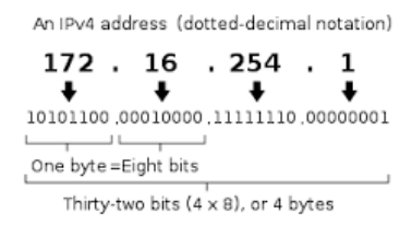
The commonly used addressing in computer networks today is IP Address version 4 or often called IPv4. IPv4 is an addressing method consisting of 4 bytes where each byte is separated by a dot, with 1 byte representing up to 255 in decimal. Thus, theoretically, the usable IPv4 addresses are 255 x 255 x 255 x 255.
An IP Address consists of two parts: the network address and the host identifier. The network address defines the network address used. The host identifier is used to define the host that belongs to that network. Hosts located in the same network address can communicate directly, whereas hosts in different network addresses require a router to communicate.
Initially, IPv4 implemented the concept of classful addressing. In this method, IP addresses were divided into classes based on the number of hosts that would communicate on that network. As networks and the internet grew, the use of classful addressing became irrelevant. Therefore, the method currently used for IP addressing generally employs CIDR (Classless Inter-Domain Routing), which is a development from the class-based method.
In the CIDR method, a / (slash) notation appears followed by a decimal number from 0 to 24 on an IPv4 address. This notation is used to define the length of the subnet mask, which then functions to separate the network address and the host identifier. For example, 192.168.100.14/24 is the IPv4 address 192.168.100.14 with a subnet mask of 255.255.255.0, where the CIDR notation 24 indicates the number of contiguous 1 bits in the subnet mask, so its network address is 192.168.100.0.
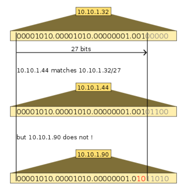
Figure 2 illustrates the use of CIDR with 10.10.1.44/27 which falls into the 10.10.1.32/27 subnet, while 10.10.1.90 is not included in it.
Subnetting#
As previously explained, an IP Address consists of 2 parts: the network address and the host identifier. In certain cases, more than one network needs to be built from a single network address. The process of dividing or splitting a network into several smaller networks is called subnetting.
The main purposes of creating subnetting are generally:
- Efficiency of the IP Addresses to be used
- Reducing network traffic congestion
- Facilitating network management, etc.
The method currently commonly used to create subnets is called VLSM (VARIABLE LENGTH SUBNET MASK). The process of creating subnets using the VLSM method begins by defining the number of hosts that will be included in the subnet. From this number of hosts, the subnet mask that will be used to form the new subnetwork address is then determined.
Routing#
Hosts connected within the same network address and subnet mask can communicate directly with each other. However, communicating with a different network requires defining a path for communication, which is often called routing. This routing process is performed on a device known as a router.
A router is responsible for providing paths to communicate to other networks. A router utilizes the concept of a table to define the paths that can be traversed to reach a specific network. This table is also known as a routing table. In implementation, forming a routing table can be done manually (static) or dynamically using specific algorithms.
To populate a routing table, the following information is required:
- Destination network address
- Address of the router handling that network
- Address of the neighboring router that can be traversed to reach the destination network
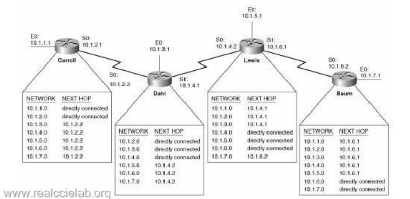
Figure 3 illustrates routers being used to connect different networks by utilizing routing tables. Routing tables are created on each router to define the paths that can be used to communicate with other networks.